
See more: Isaiah 11:6 Meaning Of And A Child Shall Lead Them Kjv, Isaiah 11:6 Kjv
GEAR SOLIDWORKS TOOLBOX HOW TO
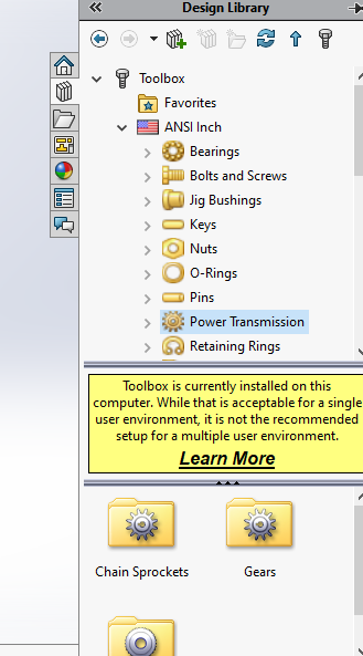
Those are How to create Spur Gear with SolidWorks and if you want to modify the gear back, it means giving tapped hole to the keyway, just modify itself with your own design. Module: 4Number of Teeth: 50Face Width: 20Hub Style: One SideHub Diameter: 69Overall Lenght : 12,7Nominal Shaft Diameter: 30Keyway : Rectangular 1Īnd after we’ve been fulfilled the parameter click the green checklist and the SolidWorks will running to process our gear design. On the image above we can see that the several gear parameter choices should be fill, and for this section, we will make a Spur gear that having a parameter like this: See more: No Visible Light Can Escape A Black Hole, But Things Such As Gamma Rays, X Rays, And Neutrinos Can. Uncheck the box called Make this folder the default search location for toolbox components. So to make them look better, you need to change the setting in the System Options Hole wizard/Toolbox. Open in SOLIDWORKS User Forum to read and respond to complete thread Feedback. can some one help me see attached parts generated with the toolbox. Open SolidWorks and create a 1 (25.4mm) cube. The toolbox will override any changes made to a toolbox part, but I think the default Toolbox gears are ugly. Ive used the toolbox to generate 2 straight miter gears (one with 16 teeth, the second with 32) to have a ratio of 2:1. Directions: Practice using the MEASURE and MASS PROPERTIES tools. The tools used in this activity are MEASURE and MASS PROPERTIES. They can be accessed using the TOOLS section in the standard toolbar menu. Then just put the parameter for gear that you’ll make. Powerful geometry tools are built into SolidWorks design software. Then click the Spur Gear and click the right side of the mouse then click Create Part.Īfter that, there will be the choices of Feature Manager on the left screen sides. After that, the kind of gear choices will appear. The first step is to click the Design Library then choose the ToolBox and then click Add-In Now. How to Make Spur Gear With SolidWorks – Solidworks Tutorial Practice and apply knowledge faster in real-world scenarios with projects.
GEAR SOLIDWORKS TOOLBOX FULL
This course and over 7,000+ additional courses from our full course library.
GEAR SOLIDWORKS TOOLBOX SOFTWARE
Software required: SolidWorks 2012 and higher. You are watching: How to make a gear in solidworks Throughout these lessons, we will cover the calculations and methods of modeling a pair of spur gears that is used in a windmill water pump engine. Let’s begin to Make Spur Gear With SolidWorks. Making gear on SolidWorks are easier than making gear on Autocad because we just need to put the parameter likes Pitch Diameter, Modul, Shaft Diameter, and etc. Now, I will make a spur gear like in the image above that having 50 number of teeth. For this time, I would like to make an article about “How to make a gear with SolidWorks software”.


 0 kommentar(er)
